
Turn-Off Methods of A Thyristor
Turn-Off Methods of A Thyristor
The term commutation basically means the transfer of current from one path to another. In thyristor circuits, this term is used to describe process of transferring current from one thyristor to another. As explained earlier, it is not possible for a thyristor to turn itself OFF; the circuit in which it is connected must reduce the thyristor current to zero to enable it to turn-off. Commutation is the term to describe the methods of achieving this.
Commutation is one of the fundamental principles the use of thyristors for control purposes. A thyristor can only operate in two modes: it is either in the OFF state, i.e., open circuit, or in the ON state, i.e., short circuit. By itself it cannot control the level of current or voltage in a circuit. Control can only be achieved by variation in the time thyristors when switched ON and OFF, and commutation is central to this switching process. All thyristor circuits, therefore, involve the cyclic or sequential switching of thyristors. The two methods by which a thyristor can be commutated are as follows.
Natural Commutation
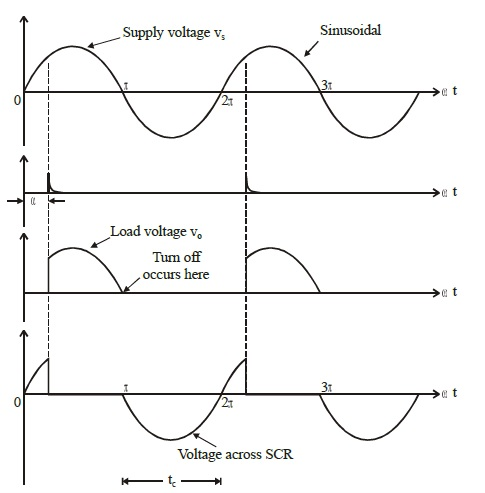
The simplest and most widely used method of commutation makes use of the alternating, reversing nature of a.c. voltages to effect the current transfer. We know that in a.c. circuits, the current always passes through zero every half cycle. As the current passes through natural zero, a reverse voltage will simultaneously appear across the device. This immediately turns-off the device. This process is called as natural commutation since no external circuit is required for this purpose. This method may use a.c. mains supply voltages or the a.c. voltages generated by local rotating machines or resonant circuits. The line commutated converters and inverters comes under this category.
Forced Commutation
Once thyristors are operating in the ON state, carrying forward current, they can only be turned OFF by reducing the current flowing through them to zero for sufficient time to allow the removal of charged carriers. In case of d.c. circuits, for switching off the thyristors, the forward current should be forced to be zero by means of some external circuits. The process is called forced commutation and the external circuits required for it are known as commutation circuits. The components (inductance and capacitance) which constitute the commutating circuits are called as commutating components. A reverse voltage is developed across the device by means of a commutating circuit that immediately brings the forward current in the device to zero, thus turning off the device. Producing reliable commutation is a difficult problem to be tackled while designing chopper and inverter circuits. The most important stage in the designing process is choosing a forced turn-off method and deciding its components.
The classification of the methods of forced commutation is based on the arrangement of the commutating components and the manner in which zero current is obtained in the SCR. There are six basic methods of commutation by which thyristors may be turned OFF.


latest video

news via inbox
Nulla turp dis cursus. Integer liberos euismod pretium faucibua


