
Class B Commutation

Class B Commutation
Figure 40 shows the class B commutation circuit which consist of thyristor T1 and L-C circuit. Class B commutation is a self-commutation process by an L-C circuit. The L-C resonating circuit is connected across the thyristor. This circuit is also known as resonant pulse commutation.
Figure 40
MODE 1 Initially the supply voltage V is applied to the circuit t = 0 and the capacitor starts to charge and it finally charged to voltage V with upper plate positive and lower plate negative. The charging of capacitor is done by the following path: V+ – L – C – RL – V_
MODE 2 When the gate pulse is applied to thyristor T1 at t = t1 and thyristor T1 will be turned on, a constant current IL flows through load and capacitor discharging current flows through capacitor. The load current IL follows though the following path: V+ – T1 – RL – V_ and the capacitor is discharged through the path C+ – L – T1 – C_
MODE 3 When the capacitor is completely discharged, it starts to charge with reverse polarity. Due to reverse polarity of capacitor voltage, the commutating current iC opposes the load current IL. Since thyristor is a unidirectional device, the net current flows through is IT1 = IL – iC. As soon as the commutating current iC is greater than the load current IL, thyristor becomes turned OFF.
MODE 4 When thyristor is turned OFF, capacitor again starts to charge with upper plate positive and lower plate negative. Whenever capacitor is fully charged, thyristor will operate in the forward blocking state and it will be turned on when a trigger pulse is applied to thyristor. It is clear from Figure 41 that if the thyristor is turned ON by applying a gate pulse and loads current flows though thyristor and load for certain specified time duration. After the specified time period, thyristor will be turned OFF due to self-commutation.
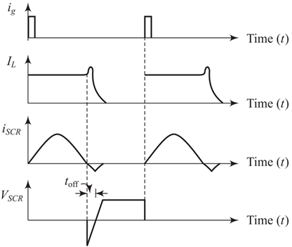
Figure 41


latest video

news via inbox
Nulla turp dis cursus. Integer liberos euismod pretium faucibua


