Class A commutation or Resonant Commutation
Class A commutation or Resonant Commutation
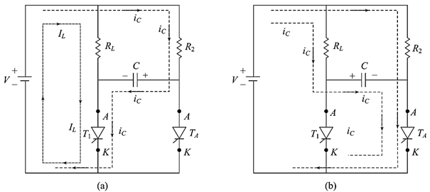
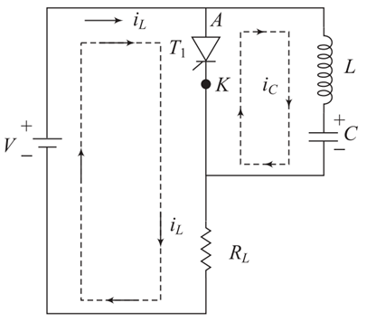
Figure 35 shows the Class A commutation circuit where L and C are commutation components and RL is load resistance. For low value of load resistance, RL, L and C are connected in series as shown in Figure 39(a). In case of high value of load resistance, C and RL are connected in parallel and then in series with L as shown in Figure 39(b).

Figure 39
When a dc voltage is applied to the circuit and a gate pulse is also applied, thyristor will be turned ON and only the charging current of capacitor flows through thyristor. After certain time, the charging current decays to a value which is less than holding current whenever the capacitor is charged to supply voltage V. The current wave from is shown in Figure 39. At point A, the current becomes zero and the commutation of thyristor occurs at this point. The time taken to turn OFF the thyristor depends on the resonant frequency and the resonant frequency is function of commutating components and load resistance. During high frequency applications above 1 kHz, this type of commutation circuit is used as the LC resonant circuit. Practically, this circuit is widely used in series inverter circuit. This commutation is also known as resonant commutation or self-commutation.
latest video
news via inbox
Nulla turp dis cursus. Integer liberos euismod pretium faucibua


