
Extension of Range using Shunts and Multipliers in PMMC
Ammeter Shunts
The coil winding of a basic movement is small and light and can carry very small currents since the construction of an accurate instrument with a moving coil to carry currents greater than 100 mA is impracticable owing to the bulk and weight of the coil that would be required.
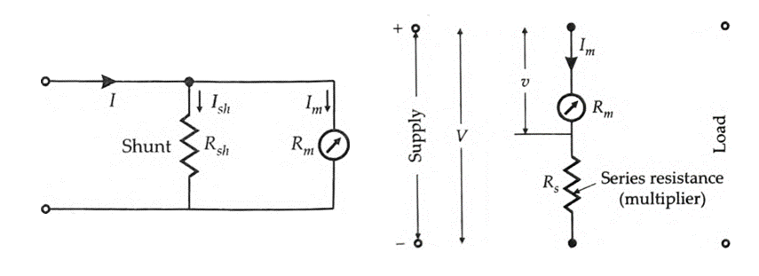
When heavy currents are to be measured, the major part of the current is bypassed through a low resistance called a “shunt”. Figure shows the basic movement (meter) and its shunt to produce an ammeter.

Fig: Basic Ammeter Circuit
The resistance of the shunt can be calculated using conventional circuit analysis.
where Rm = internal resistance of movement (i.e., the coil) Ω;
Rsh = resistance of the shunt; Ω,
Im = Ifs = full scale deflection current of movement, A;
Ish = shunt current, A
I = current to be measured; A.
Since the shunt resistance is in parallel with the meter movement, the voltage drops across shunt and movement must be the same.
$${{I}_{sh}}\,{{R}_{sh}}={{{I}}_{m}}{{R}_{m}}$$
$${{I}_{sh}}=I-{{I}_{m}}$$
$${{R}_{sh}}={}^{{{ {I}}_{m}}{{R}_{m}}}/{}_{{{I}_{sh}}}$$
$${{R}_{sh}}={}^{{{ {I}}_{m}}{{R}_{m}}}/{}_{\left( I-{{{I}}_{m}} \right)}$$
Multiplying power, $$m={I}/{{{{I}}_{m}}}\;$$
$$m=1+\frac{{{R}_{m}}}{{{R}_{sh}}}$$
Resistance of shunt, $${{R}_{sh}}=\frac{{{R}_{m}}}{m-1}$$
Construction of Shunts:
The general requirements for shunts are:
- The temperature co-efficient of shunt and instrument should be low and should be as nearly as possibly the same.
- The resistance of shunts should not vary with time,
- They should carry the current without excessive temperature rise,
- They should have a low thermal electromotive force with copper.
Voltmeter Multipliers
A d’Arsonval basic meter movement is converted into a voltmeter by connecting a series resistance with it. This series resistance is known as a multiplier. The combination of the meter movement and the multiplier is put across the circuit whose voltage is to be measured (See Figure). The multiplier limits the current through the meter so that it does not exceed the value for full scale deflection and thus prevents the movement from being damaged.

Fig: Meter with a multiplier
The value of a multiplier, required to extend the voltage range, is calculated as under:
Im = Ifs = full scale deflection current of meter,
R = internal resistance of meter movement,
Rs = multiplier resistance,
v = voltage across the meter movement for current I,
V = full range voltage of instrument.
\[v={{I}_{m}}\,{{R}_{m}}\]
\[V={{I}_{m}}\,\left( {{R}_{m}}+{{R}_{s}} \right)\]
\[{{R}_{s}}=\frac{V-{{{I}}_{m}}}{{{{I}}_{m}}}=\frac{V}{{{{I}}_{m}}}-{{R}_{m}}\]
Multiplying factor for multiplier,
\[m=\frac{V}{v}=\frac{{{{I}}_{m}}\left( {{R}_{m}}+{{R}_{s}} \right)}{{{{I}}_{m}}{{R}_{m}}}=1+\frac{{{R}_{s}}}{{{R}_{m}}}\]
Resistance of multiplier, $${{R}_{s}}=\left( m-1 \right){{R}_{m}}$$
Hence for the measurement of voltage m times the voltage range of the instrument, the series multiplying resistance should be (m – 1) times the meter resistance.
Construction of Multipliers
The essential requirements of multipliers are:
(i) Their resistance should not change with time,
(ii) The change in their resistance with temperature should be small,
(iii) They should be non-inductively wound for a.c. meters.
The resistance materials used for multipliers are manganin and constantan.


latest video

news via inbox
Nulla turp dis cursus. Integer liberos euismod pretium faucibua


