Overvoltage Protection of SCRs
Overvoltage Protection of SCRs
It is almost always necessary in a power semiconductor equipment to provide a means of limiting transient overvoltages which could otherwise overstress the semiconductor devices. To protect against all sources of voltage transients, it is necessary to protect each device individually. The effect of overvoltages is usually minimized by using the following protective elements and circuits.
(i) Snubber circuits
(ii) Nonlinear-surge suppressors
(iii) Crowbar-circuits
(i) Snubber Circuits (dv/dt Suppression)
In most power electronic circuits, protection is necessary against the effects of excessive rate of rise of forward voltage (dv/dt) across the devices, which can otherwise cause unintended breakover, leading to a malfunction of the circuit and possible to failure of the devices. The tendency to excessive dv/dt may arise from external causes such as the closing of main supply contactor, or from the operation of the circuit itself. dv/dt suppression is achieved by means of snubber circuit. The snubber circuit basically consists of a series-connected resistor and capacitor placed in shunt with an SCR as shown in Figure 22.
Figure 22
A capacitor C across the thyristor means that any high dv/dt appearing at the thyristor terminals will set up an appropriate current (C dv/dt) in the capacitor. The inductance in the circuit will severely limit the magnitude of the current to the capacitor and hence limit dv/dt. The inductance, L, limits the initial di/dt of the device at turn-on. A series inductor, either linear or saturable, may be introduced to augment the supply circuit inductance. Normally, the LCR circuit is slightly underdamped, and when a forward voltage step is applied to it, the peak voltage appearing across the device and its rate of change are both limited to acceptable values. Snubber losses can be appreciable, particularly at high-switching frequencies.
(ii) Non-linear Surge Suppressors
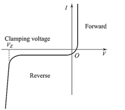
Non-linear devices having the kind of characteristics illustrated in Figure 23 are frequently used in place of, or in conjunction with, relative networks as a mean of limiting voltage surges, being so selected that they pass an acceptably small current at the normally working voltage but a sufficiently large current at higher voltages to limit surges at a tolerable level. Devices of this kind are:
(i) Varistors (ii) Selenium surge-suppressors
Figure 23
(iii) Crowbar Circuit
A crowbar can be used for overvoltage and/or overcurrent protection in both ac and dc circuits. Figure 24 shows how an SCR can be used to provide fault protection for sensitive dc power electronic circuits and loads. Whenever a fault condition occurs the crowbar SCR is triggered, shorting the supply. The resultant high-supply current flowing blows the fuse, or initiates a fast-acting circuit breaker, thereby isolating the load from the supply. Diode Df provides a current path for inductive load energy. Load current is measured by the voltage across the sense resistor R. When this voltage reaches a preset limit, that is the load current has reached the faultlevel, the SCR is triggered. The load or dc link voltage is measured from the resistor divider R2 – R3. When this voltage exceeds the predetermined limit, the SCR is triggered and the fuse is blown by the crowbar short-circuit current, isolating the sensitive load from the supply.

Figure 24
latest video
news via inbox
Nulla turp dis cursus. Integer liberos euismod pretium faucibua


