
Overcurrent Protection of SCRs
Overcurrent Protection of SCRs
As the thyristors have a restricted overcurrent capacity, special fast-acting fuses and circuit breakers are usually provided for overcurrent protection. As the fault current increases, the fuse opens and clears the fault current in few milliseconds. Before describing the fuse, it is necessary to consider carefully the requirement demands of it, which are:
(1) It must carry continuously the device rated current.
(2) Its thermal storage capacity must be less than that of the device being protected, that is I2t let-through value of the fuse before the fault-current is cleared must be less than the rated I2t of the device to be protected.
(3) The fuse voltage during arcing must be high enough to force the current down and dissipate the circuit energy.
(4) After breaking the current, the fuse must be able to withstand any restriking voltage which appears across it.
The fusing element is made of silver with one or more necks. The body of the fuse is made of ceramic material. The large contact blade or lugs facilitate connection and dissipate heat. The fusing element is embedded in a special sand which can conduct heat and serves as a quenching medium for the arc at the time of fusing. The fusing always occurs at the neck, as it restricts the flow of current. The large sections near the neck serve as heat sink and allow large current density in the restricted section of the neck. When the fault current rises the fuse temperature also rises until t = tm, at which time the fuse melts and arcs are developed across the fuse. Due to the arc, the impedance of the fuse is increased, thereby reducing the current. When the arcing is complete in time ta, the fault is clear. The faster the fuse clears, the higher is the arc voltage.
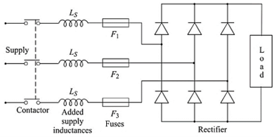
It may give adequate protection to place the fuses in the supply lines as shown in Figure 25, particularly with a passive load. However, with a live load, that is, a motor, it is possible for the load to provide the fault current, in which case each individual thyristor can be fused. In general, larger the equipment rating, the more tendency is there to fuse the devices individually. It may be necessary to add inductance to limit the rate of rise of the fault current and hence avoid excessive stress on the fuse and device. The added inductance may be in the line or in series with the individual device. However, this inductance may affect the normal performance of the converter.

Figure 25


latest video

news via inbox
Nulla turp dis cursus. Integer liberos euismod pretium faucibua


