
Class D Commutation
Class D Commutation
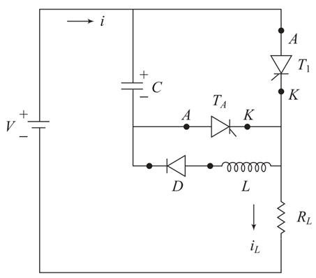
Figure 44 shows the class D commutation circuit which consists of two thyristors such as main thyristor T1 and auxiliary thyristor TA, inductor L, diode D and a commutation capacitor C. The main thyristor T1 and load resistance RL act as a power circuit but inductor L, diode D and auxiliary thyristor TA are used to form the commutation circuit.
Figure 44
MODE 1 Initially, the dc voltage V is applied to circuit, the thyristor T1 and TA are in OFF-state. There is no current flow though dc supply and commutation circuit. The conditions of T1 and TA and capacitor may be represented by T1 is in OFF state, TA is OFF state and VC = 0.
MODE 2 Firstly the triggering pulse is applied to auxiliary thyristor TA, thyristor TA will be turned ON and capacitor C gets charged. The capacitor charging current flows through the path
V+ – C+ – C_ – TA – RL – V_
Since the voltage across the capacitor C increases gradually, the current flow through the thyristor TA decreases slowly. Whenever the capacitor is fully charged to V, the auxiliary thyristor TA gets turned OFF.
In this mode, the conditions of T1 and TA and capacitor may be represented by Initially TA is in ON state, and at steady state condition T1 is in OFF state, TA is OFF state and VC = V.
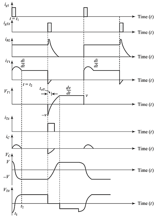
Figure 45
MODE 3 When the triggering pulse is applied to main thyristor T1, the current flows in the two different paths:
The load current IL follows though the following path:
V+ – T1 – RL – V_
and commutation current (capacitor discharging current) flows through the following path:
C+ – T1 – L – D – C_
When the capacitor is fully discharged, its polarity will be reversed. The discharging of capacitor C in reverse direction is not possible due to presence of diode D. At the end of this mode of operation, T1 is in ON state, TA is in OFF state and VC = – V.
MODE 4 In this mode, whenever the thyristor TA is triggered and turned on, capacitor C starts to discharge through the following path:
C+ – TA – T1 – C_
When the commutating current (discharging current of capacitor) becomes more than load current IL, thyristor T1 gets turned OFF. At the end of mode 3 operation, T1 is in OFF state and TA is OFF state.
Capacitor C will again charge to the supply voltage V with the polarity as shown in Figure 45. Since the commutation energy rapidly transfers to the load, high efficiency is possible in class D commutation. This commutation is most commonly used in Jones chopper circuit.


latest video

news via inbox
Nulla turp dis cursus. Integer liberos euismod pretium faucibua


