
Earth, Signal and Chasis Ground
Not the Earth Ground from Geology
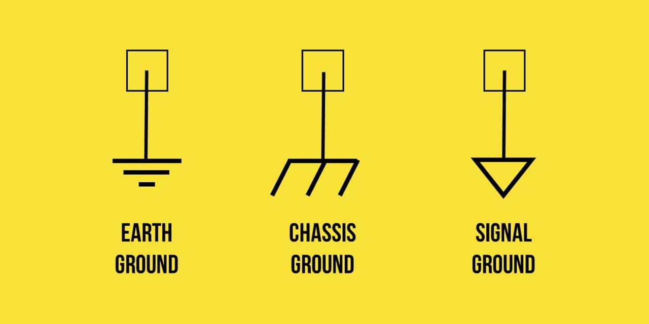
Up to now, we have been drawing circuit schematics in a fashion similar to that of the one shown in Fig. 1, where voltages are defined across two clearly marked terminals. Special care was taken to emphasize the fact that voltage cannot be defined at a single point – it is by definition the difference in potential between two points. However, many schematics make use of the convention of taking the earth as defining zero volts, so that all other voltages are implicitly referred to this potential. The concept is often referred to as earth ground, and is fundamentally tied to safety regulations designed to prevent fires, fatal electrical shocks, and related mayhem. The symbol for earth ground is shown on Fig. 3a.

Since earth ground is defined as zero volts, it is often convenient to use this as a common terminal in schematics. The circuit of Fig. 1 is shown redrawn in this fashion in Fig. 2, where the earth ground symbol represents a common node. It is important to note that two circuits are equivalent in terms of our value for Vo (4.5 V in either case), but are no longer exactly the same. The circuit in Fig. 1 is said to be “floating” in that it could for all practical purposes be installed on a circuit board of a satellite in geosynchronous orbit (or on its way to Pluto). The circuit in Fig. 2, however, is somehow physically connected to the ground through a conducting path. For this reason, there are two other symbols that are occasionally used to denote a common terminal. Figure 2b shows what is commonly referred to as signal ground; there can be (and often is) a large voltage between earth ground and any terminal tied to signal ground.
The fact that the common terminal of a circuit may or may not be connected by some low-resistance pathway to earth ground can lead to potentially dangerous situations. The common terminal of every circuit in the equipment has been tied together and electrically connected to the conducting equipment chassis; this terminal is often denoted using the chassis ground symbol of Fig. 3c. The electrical connection to earth, however, has been made (inadvertently) a nonzero resistance; it may be the table for all we know. In any event, there is no reason to expect the chassis ground to be at earth ground. A pseudo-schematic (some liberty was taken with the person’s equivalent resistance symbol) of the situation is shown in Fig. 4. If the equivalent resistance of the person is significantly less than the resistance of all other possible paths to ground… well, let’s just say not all stories have happy endings.
 The fact that “ground” is not always “earth ground” can cause a wide range of safety and electrical noise problems. One example is occasionally encountered in older buildings, where plumbing originally consisted of electrically conducting copper pipes. In such buildings, any water pipe was often treated as a low-resistance path to earth ground, and therefore used in many electrical connections. However, when corroded pipes are replaced with more modern and cost-effective non-conducting PVC piping, the low-resistance path to earth ground no longer exists. A related problem occurs when the composition of the earth varies greatly over a particular region. In such situations, it is possible to actually have two separated buildings in which the two “earth grounds” are not equal, and current can flow as a result.


latest video

news via inbox
Nulla turp dis cursus. Integer liberos euismod pretium faucibua


